A few months ago I was fortunate enough to win a Boss Katana 50 amplifier. One of the features of the amplifer is channel presets which can be switched via a footswitch. The default option for this is a 2 button item, one switching channels the other swapping banks. This means sometimes to change to a given channel you will need to push 2 buttons to swap both bank and channel.
For the 100W versions a 4 button footswitch is available allowing direct access to 4 channels on each bank, this is my DIY attempt to build my own 4 button switcher for the Katana 50.
My idea was to use an Arduino to read the inputs of 4 momentary switches, and then use this to set the appropriate connections for the channel switching and also an LED to show which channel is selected.
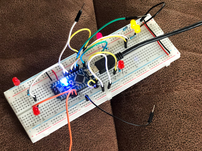
An initial design was prototyped on a breadboard. I didn’t have enough switches at this point so wires were simply shorted together to act as switches. This needed some tweaking but after a while I had a working design. The Arduino firmware was also written at this point.
Once I had a working design I used a free application called KiCad to first create a schematic, and then a PCB design. This took a few attempts but the docs where pretty good and after following a few tutorials I was able to pick up enough to bumble my way through. I really enjoyed this stage and I hope to be able to use these skills again and build upon them in the future.
Read more…
