Diy Katana 50 4 Channel Footswitch
A few months ago I was fortunate enough to win a Boss Katana 50 amplifier. One of the features of the amplifer is channel presets which can be switched via a footswitch. The default option for this is a 2 button item, one switching channels the other swapping banks. This means sometimes to change to a given channel you will need to push 2 buttons to swap both bank and channel.
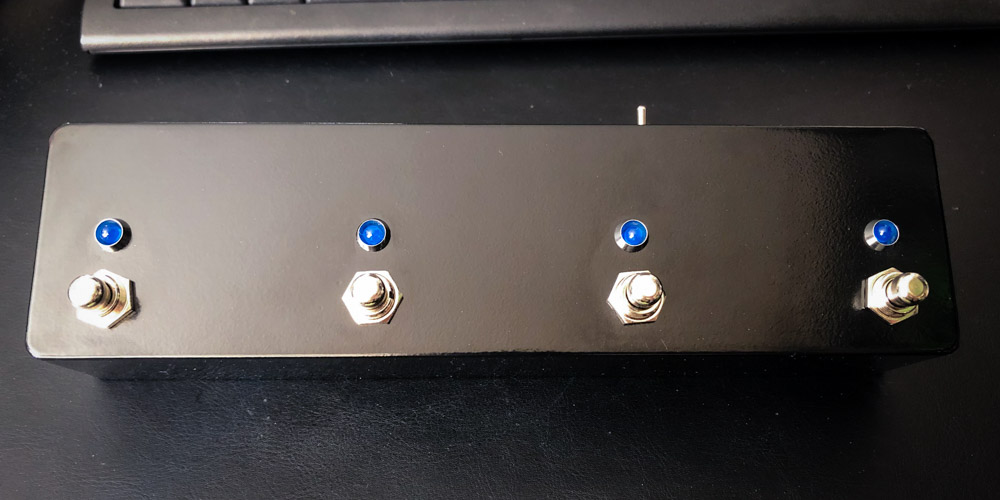
For the 100W versions a 4 button footswitch is available allowing direct access to 4 channels on each bank, this is my DIY attempt to build my own 4 button switcher for the Katana 50.
My idea was to use an Arduino to read the inputs of 4 momentary switches, and then use this to set the appropriate connections for the channel switching and also an LED to show which channel is selected.
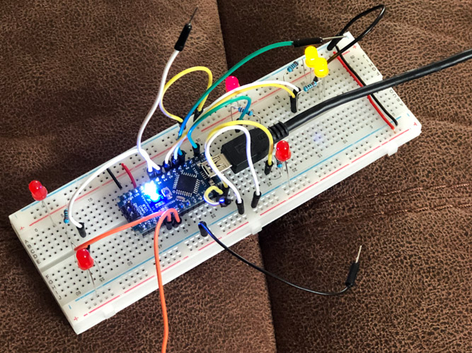
An initial design was prototyped on a breadboard. I didn’t have enough switches at this point so wires were simply shorted together to act as switches. This needed some tweaking but after a while I had a working design. The Arduino firmware was also written at this point.
Once I had a working design I used a free application called KiCad to first create a schematic, and then a PCB design. This took a few attempts but the docs where pretty good and after following a few tutorials I was able to pick up enough to bumble my way through. I really enjoyed this stage and I hope to be able to use these skills again and build upon them in the future.
To get the boards made there are a few options, but I elected to use JLCPCB in China. This company had popped a few times in a few YouTube videos over the last year. They also were very cheap for the boards and offered reasonable postage too if you’re not in a hurry. As this was my first order they also heavily discounted that postage to essentially free!
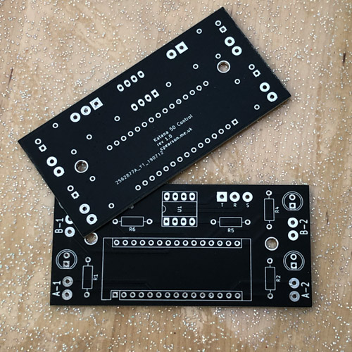
The boards came quicker than expected and were great, especially given the money. I didn’t opt for RoHS solder tinning as I planned to use a leaded solder but this is a paid optional extra if you need this. Colour options were free so I chose black rather than the normal green you see for PCBs, though white was tempting!
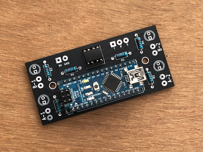
I quickly built up one board which was nice and easy. The pre-tinned pads took solder easily, though I could have designed a few pads to be a touch larger.
I designed the PCB to fit into a 1590BB enclosure which is a sort of fat rectangle with a switch in each corner. When looking for a black one on eBay I found a cheaper long enclosure which I ordered instead, a 1032L. This meant the PCB wasn’t ideal layout wise but I could fix this in wiring and firmware later.
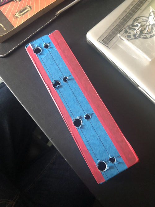
Due to the nice size and height all the components fitted inside with plenty of room. Hole locations were drawn onto masking tape to ensure accurate placement and an even look. These were then drilled out with step drills.
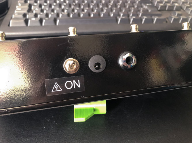
Once the holes were in place wire lengths were worked out, cut to length and pre soldered outside of the enclosure. Wiring inside a metal box is a pain so everything bar the power was done before being fitted. The power jack fits outside in so this needed to be soldered in situ. The PCB mounts didn’t stick to the enclosure very well but have worked well enough to stop the board shorting on the case.
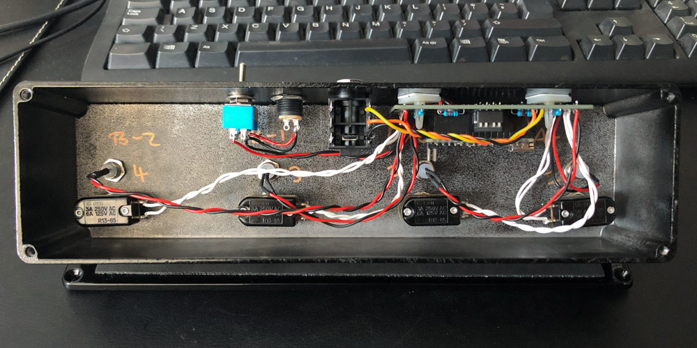
Due to the change of layout I opted to change which channels went where on the PCB to keep the wiring clean internally, rather than run them across the board to honour the original design. This meant I had to change the firmware slightly to account for this. Fortunately I had coded in a way that meant this was very simple and quick to do. This means the PCB silkscreen is now wrong for what is connected but they do tie up to what the code says.
In use the switch has worked really. The amp swaps reliably and quickly when a channel is selected. The only real down side is if you change using the amp panel it doesn’t know, but will be correct when you next swap to a new channel1. As with any project like this I have a whole list of stuff I would do differently next time but I am happy with results for a first try.
I don’t plan on selling any of these, but if you want to make your own I have published all the needed files in a github repo: KatanaSwitch. If building one yourself isn’t for you check out Bright Onion Pedals.
-
The channel settings are only updated if the channel is changed, not when a button is pressed. ↩