Cloning the Vemuram TSV808 with The Tone Geek
The Vemuram TSV808 is a sort of modified of a Tubescreamer/JanRay hybrid. It’s also incredibly high end. Initially selling for $499, if you could get one in the limited release, and are now being listed on the used market for £1200-£1800 or more.
The internet has allowed me the chance to get to “meet” and speak to people all over the world. One of those is Ryan The Tone Geek. We often talk guitars, pedals, electronics and what ever dumb stuff that comes up.
One evening Ryan sent me a photo of a Vemuram TSV808, a multimeter and a ton of hand drawn documentation. After a bit of conversation I suggested bread boarding it to check the schematic. “I find that so borinnnggggg” came the reply, and after a few more messages back and forth, I had my own copies of the board layout and first pass hand drawn schematic.
My first task was to turn the hand drawn document into a digital one that is easier to maintain and share. I used KiCad for this, which took me an evening. Something about this project had grabbed me and I just had to do it. Whilst creating this schematic I checked values against both the photos of the board I got from Ryan, but also some found on google. As I was doing this my wife re-drew the board layout to be a bit more legible where some items had been squashed together.
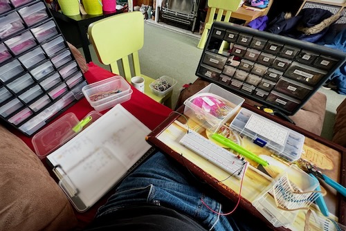
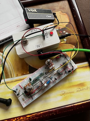
With a schematic in place it was time to try bread boarding it. I printed the schematic to allow me to mark what was done, and with some pretty cheap parts I had in stock I got started. Whilst I had most parts, some had to make do with what I had to hand and was close enough. I started with the power section as everything else will hang off it. Followed up with building up the first op amp stage (the gain and clipping circuit) on the bottom half of the board, then the tone stack and 2nd op amp stage (I think amplification and tone shaping) on top half. I started this at 4pm and by 6pm I had a working, reasonably close clone of the TSV808, 3 days after first getting the documents. Not only that but it worked, and sounded great.
With the first prototype complete I ordered the parts I did not have to hand and fixed an issue where I had the Gain pot backwards. Due to the COVID parts shortages I couldn’t get trim pots with thumb knobs and made do with some that need a screw driver.
The next step was to start building a BOM, or more accurately 2.
The first was an accurate one using as many accurate parts from the original as possible. This was the start of the mouser BOM, I found the film caps, DALE CMF55 resistors and then picked out a set of Koa Spear resistors for the rest 1. Ryan managed to find the correct poly caps and some really nice polymer capacitors to replace the custom electrolytics used.
The 2nd BOM was a more “budget” Tayda bom, though the Mouser one isn’t a huge amount more, and you’ll need to order some bits from Tayda such as the pots and enclosure anyway. This swaps the majority of parts for more standard ones, though by no means rubbish, and I selected these to allow me to build a reasonably close version but $10 or so cheaper per pedal. The major changes where standard electrolytic caps, the mica caps were swapped to ceramic, and the tone capacitors from rolled to dipped polyester film.
Spoiler: Both BOMs basically sound the same ± pot tolerances.
At the start the OpAmp was still unknown, so the tried and true 4558D(D) was chosen. Mouser stock the 4558DD if you want some of the fancy ones. Later that was found to be the OPA2134.
Whilst all this was happening Ryan was doing his thing with the PCB layouts. This is the point where the 9mm trim pots were chosen to replace the internal trims, but for the most part this is where Ryan excels so he was always ahead of me! He’s documented his side of all of this on his site.
At this point we had all we needed to order PCBs. For reference this was less than a week from those first photos changing hands.
Before the order went in I did one last thing. I hate hand wiring foot switches as it’s too fiddly, so created a small daughter board to match the layout Ryan did.

Pretty soon stuff started arriving and I was able to build up the first ATS808 using the Tayda BOM to prove it. It worked! but there was 1 small issue: the volume pot was backwards. This was fed back to Ryan and fixed going forwards. Fortunately this is an easy fix with some wire to “flip” the pot.
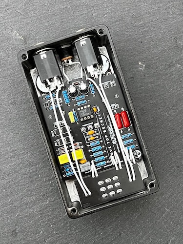
I used this for a while before building a 2nd using the accurate parts into a hammered copper enclosure which looks fantastic. I still haven’t gotten round to ordering the correct OPA2134 chip so I am currently using a 4558DD.
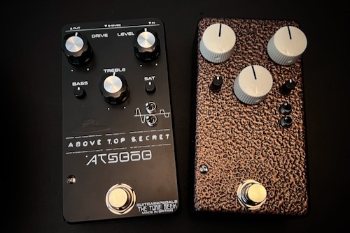
If you wish to buy your own ATS808, either as a kit or built, check out The Tone Geek Shop where you can purchase not just the ATS808, but also a number of other products that are all excellent. I have the VS10, mk1 AP2 as well as the Black Triangle (which I still need to build).