DIY Boss BD-2 Blues Driver "Keeley Mod"
One of the more famous pedal mods is the “Keeley Mod” that Robert Keeley used to do to the Boss BD-2. This modded pedal has been used by a number of great players including John Mayer which is how I’ve ended up here. Keeley no longer modify pedals, so you either have to go hunt down a used one, and they will only get more expensive, or you can get a Super Phat Mod, which is essentially a true bypass modded BD-2.
Being the person I am rather than buying an old pre-modified pedal I decided to buy a standard pedal used and modify it my self.
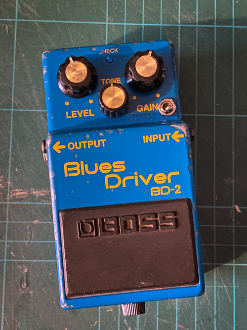
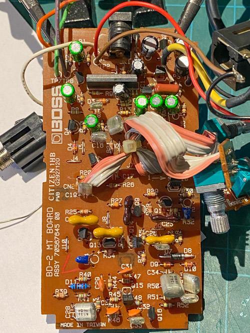
If you want to do this your self then there is one gotcha. A year or so ago (2018/9 ish) Boss changed from through hole to SMD components for the BD-2, which make this kind of mod impossible 1. So hit eBay and look for an older pedal. The ones you want have the power jack in the middle of the back like below, not the ones where the jack runs along the base plate.

Older pedals with blue boxes will be fine, the change happened during the current black boxes so you can’t just go “black box is no good” as earlier ones will still be able to be modded.
Before we start: thanks to Ryan “The Tone Geek” who did most of this research and I am just following from his work and a few google searches.
Table of Contents
Boss BD-2 Blues Driver Mods
This is not all-inclusive in what can be done to the Blues Driver. It is meant to give an idea of where the tone can be improved or changed. All of the changes are subtle but when packaged together offer a nice improvement.
D3 Change this 1SS133 to a different (1N4002) diode for asymmetrical clipping. This adds second order harmonics. This adds to the tube type sound. I like the sound of this change.
D7 D8 D9 and D10 Change 2 of of these diodes from 1SS133 to a single 1N4002. More second order harmonic distortion. Although the change is slight, I like it. We actually take out one of the two pairs and replace it with a single 1N4001.
C1, C7, C6, C12, C13, and C15 Change this electrolytic capacitor to a 10uF Non-polarized caps. Non-polarized caps sound better . I like these anywhere there is signal coupling at this high a value.
C14 Increase input coupling capacitor value to 0.1uF for increased bass response from your guitar.
C100 Here is where we can affect the tone control. I prefer a little more lower-midrange and bass frequencies through the tone section. You can increase the lower frequencies by increasing the capacitor value to 0.033uF. Install a switch to add a 0.068uF cap in parallel with this value for the Phat Mode!
Most of the ceramic caps are changed to Expensive Silver Mica (available through Small Bear Electronics www.smallbearelec.com or www.mouser.com or www.digiley.com[sic]). This is what makes our mod sound so good. A noticeable reduction in noise. An increase in the smoothness and no harshness left. This type of upgrade is not found in anyone's mods. The best sound is right here.
My BD-2 Pedal
My personal pedal is from 1996, they launched in 1994 so it’s reasonably early. I bought it “spares or repair” from a seller in Japan as it was the cheapest way to get one. Or so I thought! I had forgotten about the tax changes post Brexit so after those were added it ended up costing more or less the same as the ones for sale in the UK. So not a big saving as hoped but a story at least.
The only issue with the pedal I found seems to be dirty jacks. Once cleaned with some Servisol Super 10 it has been behaving well. This is probably worth doing on any used pedal when it comes in just to help with reliability.
Other than that it has the typical old Boss pedal patina and the knobs are a little loser than ideal, but fine.
Being an old one I was hesitant to modify it but Boss must have made thousands of these each year so it’s not exactly a rare piece and is hardly in museum condition.
List of Changes
Over the time the mod has changed a little, my mod is based on a specific example but takes into account the research. In short there is not a single exact set of changes, but they are all reasonably close to each other. Note my mod isn’t including the D3 change listed above as that wasn’t in the pedal I have access to for reference. I also undid one change that I found caused an issue, see the note below.
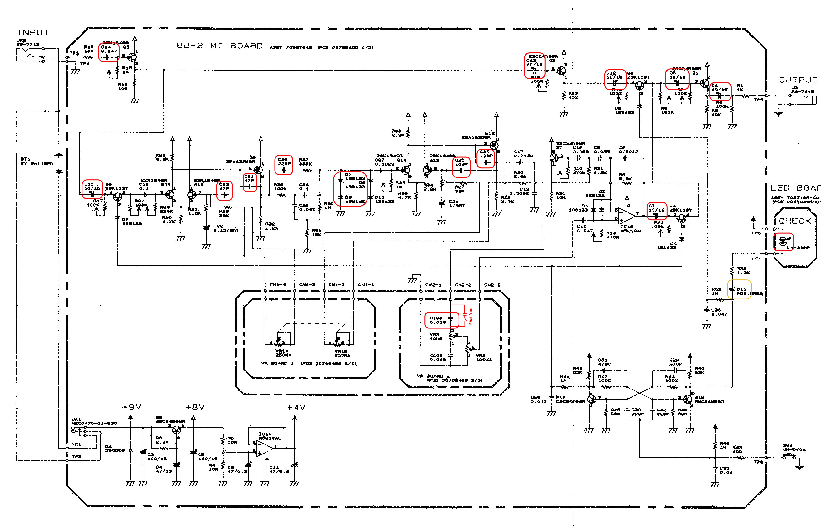
(Click the image to open at full size)
| Reference | Boss Value | Keeley Mod Value | Notes |
|---|---|---|---|
| C14 | 0.047uF (47nF) | 0.1uF (100nF) | Input capacitor lets more bass into the circuit |
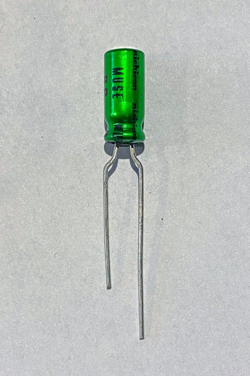
| C1 C6 C7 C12 C13 C15 | 10uF Polarized Electrolytic | 10uF Non Polarized Electrolytic | Non-polarized caps “sound better” |
| C20 C25 | 100pF 10% ceramic | 100pF 5% Silver Mica | Lowers noise |
| C21 C23 | 47pF 10% | 47pF 5% Silver Mica | Lowers noise |
| C26 | 220pF 10% | 220pF 5% Silver Mica | Lowers noise |
| C100 | 0.018uF (18nF) 10% | 0.033uF (33nF) | Adds “a little more lower-midrange and bass frequencies through the tone section” |
| - | - | 0.068uF (68nF) or 0.082uF (82nF) | “Phat mod” the switch adds this in parallel to C100 for more bass * |
| D7 D8 | 1SS133 | Single 1N4001 | Adds second order harmonics |
| LED | Red | Ultra bright blue | Better visibility |
| D11 | 11K | Yes they really did replace a diode with a resistor! This is for the LED circuit. ** |
* The phat mod capacitor has been both 68nf and 82nf, the larger the value the more bass you’ll get so it’s probably worth testing to see which you prefer.
** I actually reversed this mod and put the factory diode back. With the resistor in place the LED was always on dimly which the diode fixes. I can only assume this uis due to characteristics of the specific LEDs Keeley used. If you want the LED dimmer change R39 for something like a 3.9K or a 10K depending how much you want to dim it.
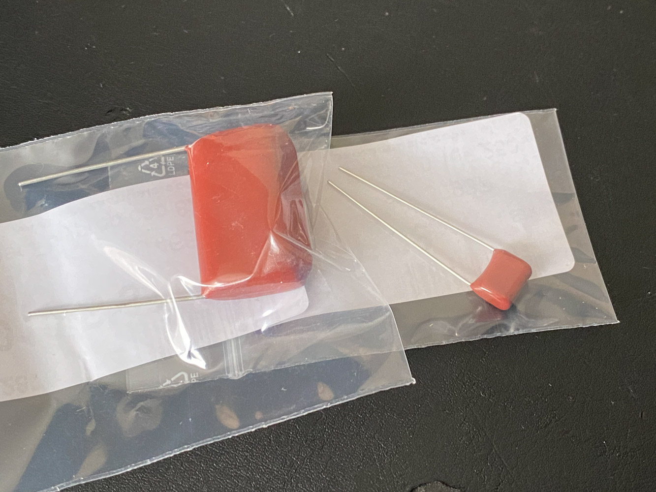
I will be using quality branded parts for all of these changes. Cornell Dublier for the silver mica, Nichicon MUSE for the non polar2, Panasonic film capacitors, On-Semiconductor didoes and Royal Ohm resistors. The only exception to this is I messed up ordering the 82nF and got a huge 600V one for an amp, so I am using a 68nF Mylar ‘Greenie’, I may change this later. For the switch I have a Hongh branded switch, this is a company set up by an ex-Alpha engineer and I have found all of their parts to be very similar in quality and feel.
Whilst you could use other cheaper items, the list isn’t very long and so you’re not going to save a huge amount so may as well use the high end stuff if you can get it.
Tools
On top of the replacement components you will need the following tools:
- A soldering iron, or soldering station.
- Solder, preferably leaded as it flows easier and helps when removing the lead free solder from the board.
- Solder wick, to remove the old parts (MG Chemicals, Hakko)
- (Optional) Solder pump (I like this Engineer SS-02)
- Cutters to trim the components
- Wire strippers (These have proved good on a variety of wire Jokari Super 4)
- Small diameter heat shrink (1.5-2mm will be fine) around 5cm long.
- Small gauge wire around 0.25-0.35mm²/22-24awg, around 5cm long.
The Mod
Disassembling the pedal
For things like this I like to completely remove the circuit from the pedal. If you are skipping the phat mod this is probably unneeded but I dislike the idea of drilling into the enclosure with the important bits in the way. This probably is not how Keeley did it as it’s slower.
- First remove the knobs, they should just pull off. Mine are a bit loose so came of easily but if they are proving tough use two small tea spoons to gently leaver them off.
- Remove the back plate, and put this and the plastic shield to the side. Use a #2 philips screwdriver, not a pozidrive and do it by hand. They are actually JIS #2 but you almost certainly don’t have one of those and a philips is a reasonable fit, just be gentle.
- Put the 4 back plate screws into a cup, bowl, something that will stop them going missing. You won’t be able to replace them like for like so losing them is going to suck.
- Unscrew the nuts for the side jacks using a 12mm socket and put them in the cup along with the washers. I like to use some 3D printed finger sockets as they save me from damaging things, but a normal socket works too just hold it in your fingers. Try avoid adjustable spanners, they have a habit of damaging things.
- Remove the 3 nuts for the pots using an 11mm socket, along with the washers.
- Carefully lift the board away, the DC jack will be slotted into the hole in the enclosure so will need to be slid out slightly.
- Use a PH2 screw driver and remove a single screw holding the LED daughter board in place.
At this point you can remove the circuit from the case but it will still be held to it buy the battery and switch wiring. Take care removing the jack sockets as there is a star washer on each to put in the cup.
If you wish you can stop disassembly here, but take care when drilling for the switch that you don’t hit anything.
To remove the remainder:
- Push the switch up from inside the enclosure and out. Gentle but firm pressure is needed.
- Carefully de-solder the 2 wires from the switch. The wires are just hooked over, once the solder is removed with a sucker a light tough with the iron will help it come away. The purple wire on mine was glued in place, I carefully cut the glue with a scalpel.
- Push the battery clip through the hole.
Changing the components
Before starting prepare the electrolytic capacitors. Using a pair of needle nose pliers bend the legs as shown, you want about 5mm between them so they fit well but leave a little wire for later.
This isn’t needed for the mica capacitors, the spacing is slightly wide but they fit close enough leaving a short gap to the board. The film caps will just drop into place.
There’s 2 ways to do this, remove all parts first (which is what I actually did) or a part at a time as documents below which is probably less confusing if you’re less experienced.
For each component do the following:

- Locate the component to replace on the circuit board. Note C100 is on the board with 2 pots on it.
- Now find the pads for that on the back of the board. Take your time here so you don’t remove the wrong thing!
- Apply a little new solder. This will heat the join a bit and adds fresh flux, helping the solder flow better for removal.
- I like to remove the bulk with a solder sucker. Heat the joint and quickly suck away the excess. Don’t hold the iron on too long or the pad can lift away from the PCB.
- Re-tin your iron, go a little heavy, and using some solder wick apply the wick to the joint and then apply the iron. If you have adjustable temperature, I also find I need to turn up the heat a bit for this. Watch the solder soak into the wick. Don’t hold it too long or the pad may lift. Also take care to remove the wick and iron at the same time so that the wick doesn’t stick to the pad and try to pull it off.
- With the solder removed, if you’re lucky, the part will fall out. If not heat the pads and gently wiggle the part until it comes out. Boss folded over the legs on most components so you may need to carefully bend the leg up with the iron tip to free it. This isn’t “good practice” but it’s also the easiest way to do it in my experience.
- Use some solder wick to clean the pad of excess solder if needed.
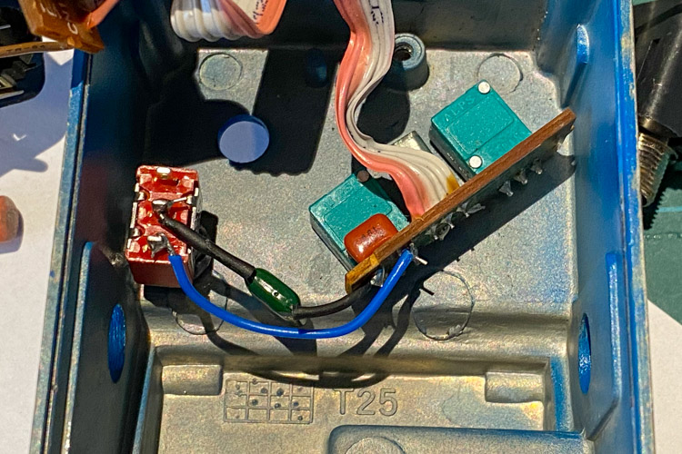
- Fit the replacement component. Ensure you leave a short amount of leg on the component side, this will allow you to reposition parts later. Take care of polarity of the diodes and LED and make sure you match it with the new parts. For the 1N4001 span both the old diodes (see image below if needed).
- Resolder the new part and trim the leads. For capacitor C100 on the pot board do not trim the leads yet, we will do this later when we add the phat cap.
This photo shows D11 replaced with an 11K metal film resistor, this was later swapped back to the original diode.
Drilling the enclosure
This is reasonably straight forward but I could have done a better job.
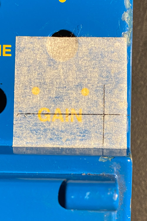
- Put some masking tape on the face to the right of the word “Gain”.
- Mark a line along the center of the word Gain, I found this to be 7.5mm from the bottom edge.
- Mark the point 5mm from the N in gain towards the edge.
- Centre punch the cross.
- Drill out with a small diameter drill bit as a pilot hole, I used a 1.8mm. This is where I went wrong as even with the punch it drifted about 1mm down. Not a disaster but not the position I went for. A better center punch mark would probably have helped reduce this. Once a pilot hole is off you’ll struggle to correct it.
- Work your way up to a 6mm hole, I went 1.8mm, 2.5mm, 3mm, then swapped to a step bit for 4, 5, 6mm.
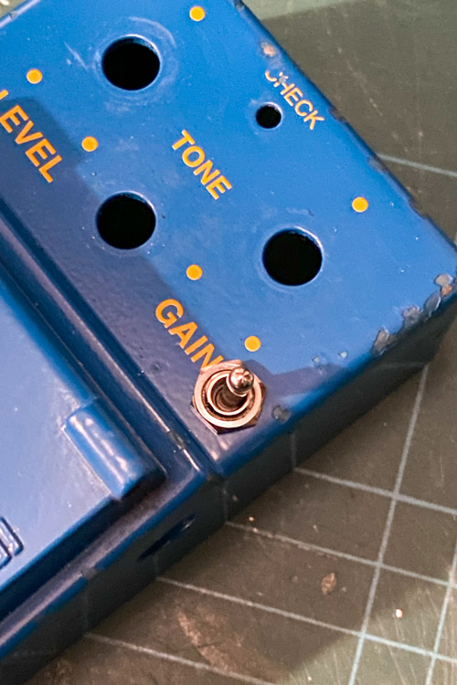
Check that the switch fits in the hole. I chose to omit the external washer and set the nuts so that the out side one is mostly flush and hides the thread.
Wiring the Phat capacitor
- Take the short length of wire and strip around 5mm off one end.
- Twist the strands and lightly tin the end.
- Bend a small hook half way down the tinned end, this will hook over the end of the leg of C100.
- Hook over the wire as shown above and solder in place.
- Trim any excess wire.
- Bend the legs of the capacitor to form a straight “wire” as above.
- Slide around 1cm (~3/8 inch) of heat shrink onto each leg of the capacitor and bend in a hook at each end.
- Hook one end of the capacitor over the leg of C100 and solder.
- Trim the legs of C100. You may want to leave a little spare in case you want to swap the phat cap in future so you have a bit more to work with.
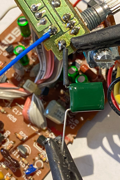
- With the switch and pot board in place, hook the free end of the capacitor into the middle switch lug and solder in place.
- Take the wire and run it along side the capacitor.
- Trim to length, the strip and tin the end as before.
- Hook through the bottom lug on the switch.
- Trim any excess wire.
Re-assembly
Assembly is the reverse of disassembly as the Haynes manuals used to say.
I started with the pots, then followed with the LED board. Next add in the jack sockets, remembering they both need a lock washer on the inside. Take care when fitting things back as whilst there is spare wire there isn’t tons. Also whilst swapping things you make have looped wires though each other, if so you will need to feed things through carefully.
Feed the battery clip back through the hole followed by the 2 wires for the switch. Resolder the wires to tha back of the switch. I added a dab of hot glue to replace the cut glue on the purple wire. Carefully push the switch back into place taking care not to pinch the battery clip wires.
Finally offer up the main board. You will need to tuck the jack socket in first then lower the front, and be gentle. Some of the new components may foul on the switch or other parts, this will mainly be the 10uF electrolytic capacitors. If this happens look under the board and see what is hitting. For me it was mostly the caps on the switch side and the new C14. Gently bend these away from what they are hitting and the board should more or less drop in.
Lastly put back the plastic insulator, screw on the back plate and push on the knobs.
You’re done, go test it out!
Demo
This is a quick demo, not sure it shows a lot and I’ll apologise for the playing. I’m a better builder than I am a player!
Phat mod, erm mod
Surprising to myself I quite liked the phat mode on, but it’s reasonably subtle. I maybe should have gone for the 82nF for a little more of a change. It’s possible to fit both (or any 2 caps of your choice) if you want to.
To do this you will need a SPDT switch but with on-off-on switching. Attach both capacitors to the same point on C100, then attach one capacitor to each of the end lugs. The wire connects to the center lug.
With the switch in the centre (off) you will have no phat cap in place. When toggled you get one of the phat caps of your choice. The way the switch works you will get the opposite lug to the switch, e.g. if the toggle is down on the outside then you get the top lug. I’d probably put the 68nf to the lower lug, and the 82nF to the upper lug. This would give lower bass, off, more bass top to bottom.
I may well do this next time I order some components.