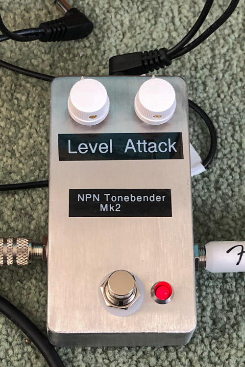
DIY Tonebender Fuzz
Late last year I started re-learning the guitar. I’ve been learning using online lessons by Justin Guitar. I’ve been slowly upgrading my equipment, buying a small practice amp and a nice PRS SE Standard 24 as rewards for my progress. But the time came to start playing with effects pedals!
Being the sort of person who I am I decided to build a DIY one. After a period of research online I decided to build a basic Fuzz, but using NPN transistors rather than the more traditional PNP transistors to allow me to use a mains adapter. This turned out to be a smart move.
The original design for this pedal is amongst the very oldest dating back to the 1960’s being used by greats like Jimmy Page of Led Zepplin. The version I have built is based on an interpretation on Guitar FX Layouts which uses stripboard to remove the need to etch a PCB.
The design calls for PNP transistors and a slightly odd positive ground configuration. This means you can’t use a mains AC adapter chained with other pedals as it would cause a short and break something. Back when the pedal was designed in the 60’s this wasn’t an issue, the PNPs were a better choice and power was a 9v battery so no shorting issues.
To mitigate this I swapped to use NPN transistors which allows me to reverse the power connections to remove all the power issues. The only other change needed is to swap the polarity of the electrolytic capacitors to stop those going pop.
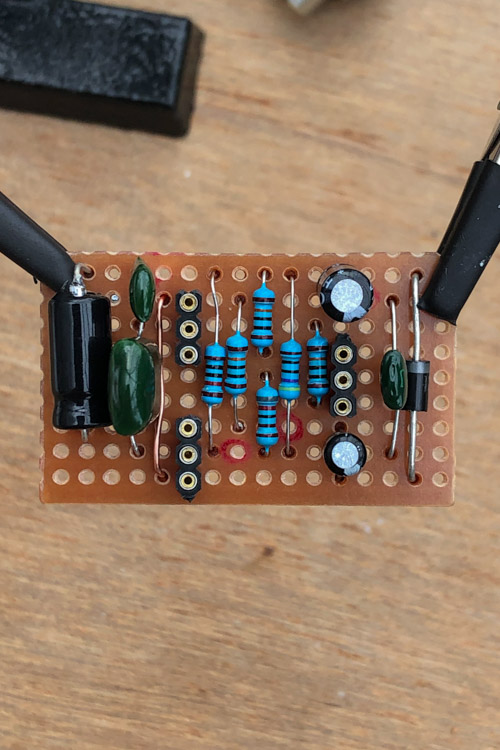
Building the main board wasn’t too complicated and my soldering skills came back fairly fast once I got going. I did have a lot of issues initially adding the wiring. I set my iron too hot which caused a lot of damage to the sleeving, so many needed doing several times. Dropping the temperature down helped a lot but slows progress dramatically.
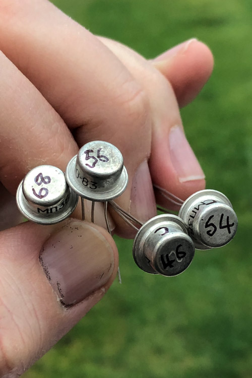
The transistors I used are NOS items from Soviet era Russia, these ones came from Bulgaria via eBay. The numbers on them represent a gain value for each1 and are really all a little low for what I need. Making the best of the situation I used the 54 & 56 for the first stage as a matched pair and the 68 for the final amplifying stage.
On first fire up the pedal didn’t really work. It produced sound but it was incredibly quiet. After some time debugging the circuit it turned out I had a dead volume control. I probably killed it at some point during the build.
I also discovered I had the 2 positive connections on the mains adapter swapped. Connecting the mains disconnected the power completely, where it was supposed to disconnect the battery to stop it blowing up when using mains power.
So back out with the soldering iron to replace the volume control and the DC socket. Working in the small enclosure to replace things was far more difficult than fitting it all in the first place.
With all the components swapped it worked! After a bit of playing about I put the back on to try it on battery to give me more freedom.
Nothing…
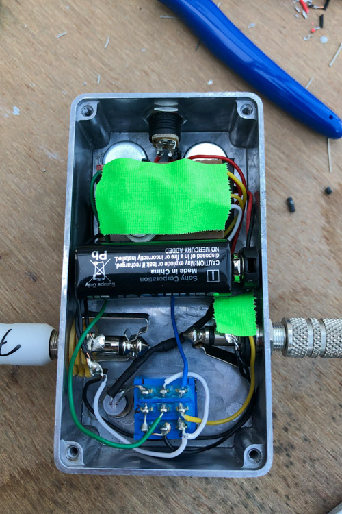
Lots more debugging follows. Checking the circuit, covering stuff in bright green gaff tape to cover potential shorts. Then it pops into life. A bit more faffing about showed there was a bad connection somewhere, with a bit of shoving about the circuit would either come to life or die.
I’m still not sure what exactly is broken. I could be the manhandling during the repairs broke something, a bad solder joint or maybe moving it is causing a short. In the end I decided it wasn’t worth the time debugging any more. I removed the battery to make space, shoved it about until it worked and just put the back on. This means I can’t use battery any more but at least it works.
Despite being far from perfect I really enjoyed making the pedal. I am tempted to rebuild it again using a new circuit board, I’d only need to order new potentiometers and maybe a new enclosure. I’d probably also use a more flexible wire. Due to how I attached the transistors using sockets, rather than solder, I’d be able to reuse them on the new build.
If I rebuild the pedal then I’ll probably make a couple of changes. A different attack control value will give more range to the control. I might also try to bias the final transistor as well rather than relying on a fixed value in the design. Ideally some higher gain transistors would be nice, and should sound better, but I don’t fancy buying a bag of 50 to find those 3 that I need.
-
This meant building a second simple circuit to test and evaluate. ↩