Using SVG2Mod to generate silkscreen images for KiCad from Inkscape
Recently I’ve been working with KiCad to design some PCBs. On some of these I have added a small logo or mono image using the built in converter that comes with KiCad. This tool allows you to take any image, colour or mono, and convert it into something you can add to your PCB.
Whilst this works the tool isn’t great and does loose a significant amount of detail when converting things.

For a recent project I wanted to make a face plate using a PCB as it’s convenient, and should be pretty durable. Sadly the built in editor wasn’t giving me results I was happy with for something that will be much more visible than normal.
Some research found a tool called SVG2Mod 1 which will convert an SVG into a .kicad_mod file that I can use.
Installing SVG2Mod
You’re going to need to use a command line, and Python3. If this means nothing to you then maybe time to stop reading.
I used WSL on Windows 10, but the same rough idea will work on linux and macOS.
First I needed Python3 and pip installed with the following command, macOS ships with Python 3 preinstalled so this isn’t needed.
sudo apt update
sudo apt install python3 python3-pip
I also needed to close and reopen my terminal now for things to take.
Now install svg2mod using:
pip3 install svg2mod
Now we are ready to rock and roll.
Using svg2mod
This is actually pretty simple, but you need to have your SVG drawn correctly. First only really paths are supported, theres “partial support” for rectangles and circles. The easiest thing to do is once you are happy with your design convert it all to paths using Path > Object to Path and Path > Stroke to Path.
This done run the tool and it will generate a mod file!
svg2mod -i input.svg -p 1.0
(run svg2mod for the input file input.svg with a precision of 1.0)
If you look at the docs there are lots of options you can use like -o for the output name or -c to set the 0,0 reference to the centre of the generated file.
Fixing the errors
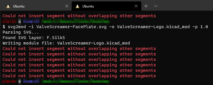
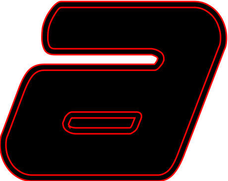
Not just with A but a good example, 0 is the same as was a polarity symbol I drew.
I used a font which was just the outlines, with no fill. The way that the paths for this were generated caused an issue in svg2mod and so you will need to fix these. The easiest way to find out what objects caused an error is to add the generated image to a pcb and see what isn’t right.
This is a worked example to fix the ‘a’ I had. This just a lower case which I ran Path > Object to Path on. Red shows the stroke, black the fill.

Select the affected object with the edit path tool (F2) and select Path > Break Apart. Everything will probably go solid now and look horrid. Things are easier to see here as I have set the stroke to a different colour.
To fix this you need to select the “pairs” of strokes that formed the shapes and then use Path > Difference. Do this for all objects and you will get a clean set of paths the tool can handle.

This shows it in action and is probably far easier to follow.
Quality
The quality of this tool isn’t perfect, but it can’t be. The pcb files can only handle so much precision and accuracy. The way it works is but creating lots of short straight lines to simulate curves, which when printed small on the PCB will look fine.
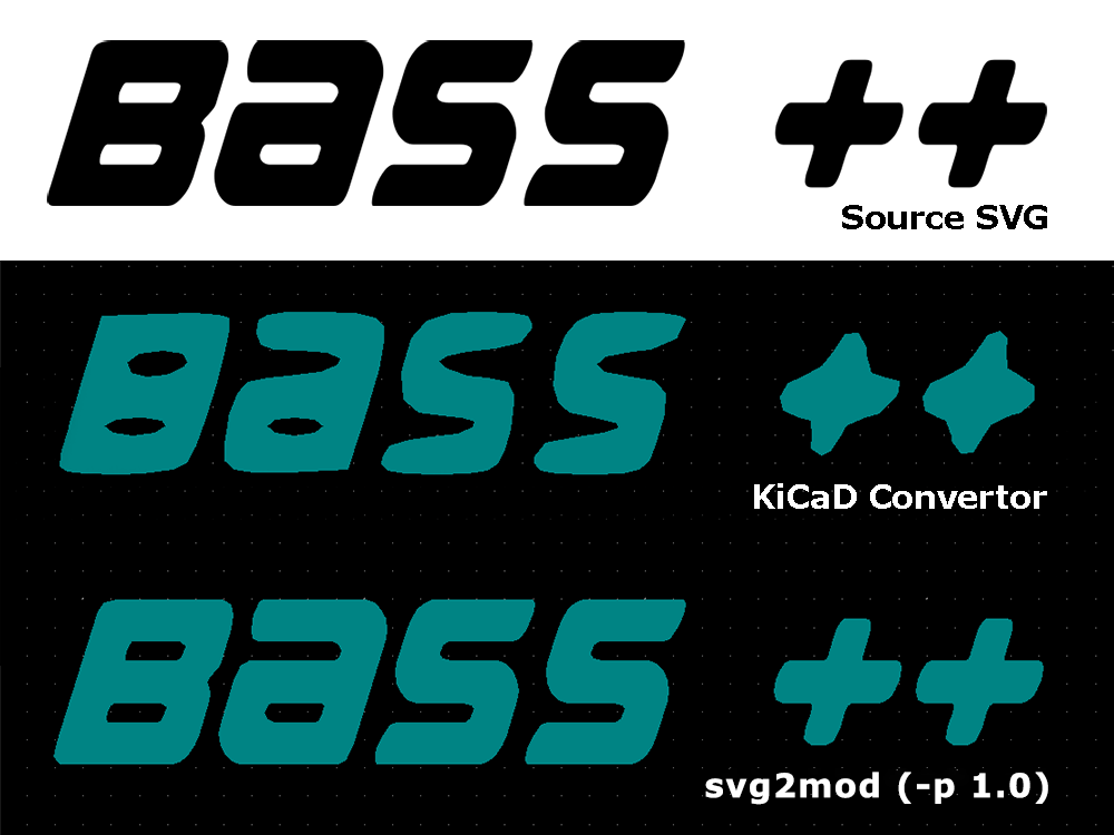
You can see that the quality from the KiCad tool leaves a lot to be desired, but the svg2mod (-q 1.0) gives a very reasonable result. Bare in mind these are going to be about 1.5mm tall when printed so we are very much zoomed in here.
svg2mod has a precision argument -p. The default seems to be 10.0, and the example suggests 1.0 but there is no documentation on what the range is and what to expect to change.
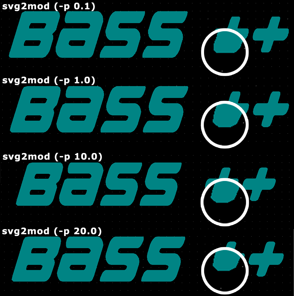
I ran some tests lower values give higher quality. The lowest I tried was 0.1 and up to 20.0. At 0.1 there was very minimal detail loss, which creeps in at 1.0 and by 20.0 is a little more noticeable. Even with this said you can only see this when zoomed right in, 1000% or so is what I am using to look at these differences. At 100% scale all of this is academic. If you’re struggling to see the difference you can see the rounded corner at the bottom of the + become more straight edge chamfers.
Given the size that these will be rendered at 1.0 is probably the correct value. However 0.1 doesn’t seem to slow down the software so perhaps it’s worth trying just to give the best possible result.
-
Note this isn’t the original version, but a fork. The original version is now no longer maintained but this version is. ↩